This article is intended to give a general overview of stamp perforation relating to British stamps, without going into too many technical details:
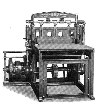
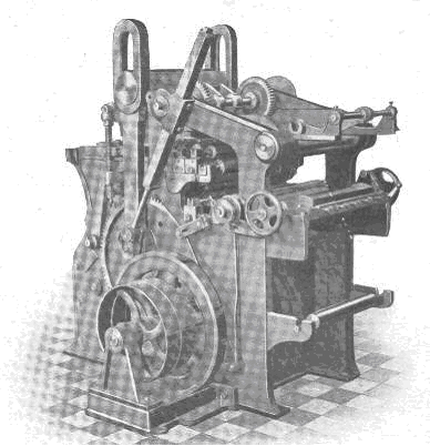
George V era perforating machine
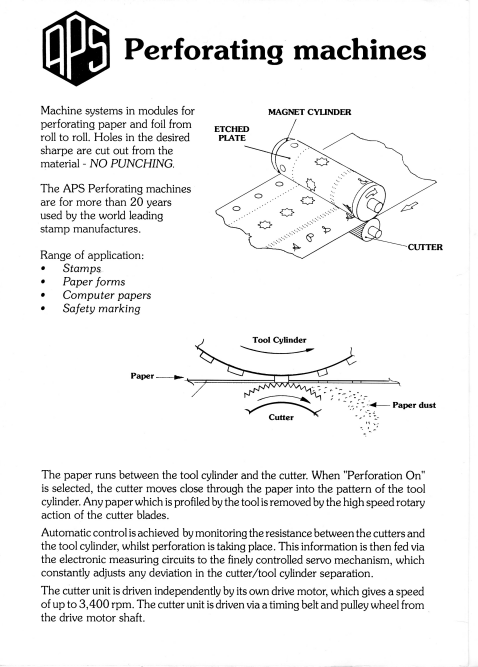
Stamps have been perforated by machines, with pins, for almost 150 years, although recent developments mean this no long applies. Today most stamp perforation is carried out by the ‘Swedish’ grinding method, which consists of a cylinder with small studs on it, and a grinding tool. The grinding tool rotates at high speed, grinding the perforation holes into a fine dust, which is extracted by vacuum, as the sheets pass between the cylinder and the grinder.
Traditional perforation was carried out on machines which had changed little since the first machine produced by Archer back in the 1850s. The perforating head consists of three basic parts, the Die Plate(2), the Stripping Plate(3) and the Pin Plate(4). The pin plate carries pins of the desired thickness in whatever configuration needed and may be for a single line of perforation, a complete row on a single pane, or on a double pane of two sheets side by side. Originally only a single comb was used and up to seven sheets could be perforated at a time. With continuous perforation, which came later, only a single thickness of paper was perforated.
The pins pass into the die plate through the stripping plate, which holds the sheet down during perforation and then ‘strips’ the paper from the pins on the return, hence its name, the paper passing between the stripping plate and the die plate. The base of the hole in the die plate is enlarged to allow free release of the perforated paper, which is collected in the base to be weighed as part of the check that all paper issued had been accounted for.
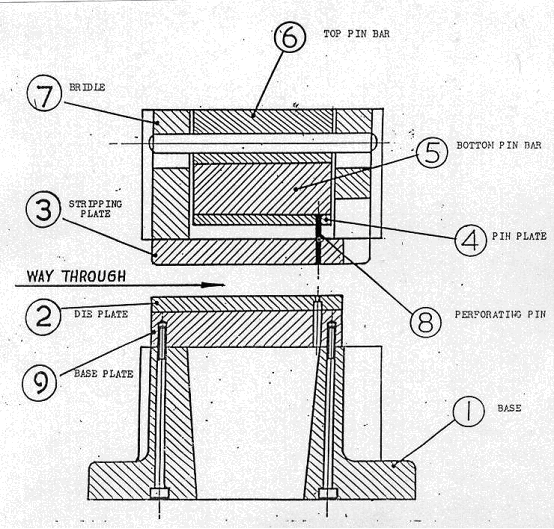
Diagram of perforating head
To ensure exact registration on all the main parts used in perforation (ie 2, 3 and 4) these were drilled from an original steel Master Plate, which was also used to produce any replacement parts that might be needed in future years.
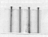
Sheets were fed into the machine through the feed table by means of the Register Pins (illustrated). Two pin points were drilled in the supporting plate of the stamp printing plate, protruding slightly above the printing surface, and these pierced each stamp sheet during the printing operation. These points could be at each side of the sheet or top and bottom. Sheets were then pinned up to the matching pin points on the feed table to ensure exact register. Delivery grippers at the back of the machine gave movement to the stamp sheets, bringing each line of stamps into correct register with the perforating comb.
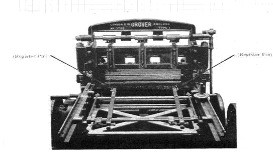
The feed table top has been removed to illustrate the register pins
Register pin point in side margin
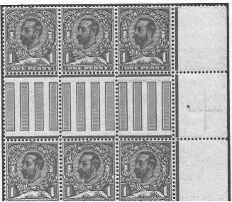
When continuous perforating of stamps produced in reels, instead of sheets, began, initially only at Somerset House for stamps in rolls, but more generally from 1924, only a single comb was used but from early 1928 a double comb was introduced. With the introduction by Harrison’s of photogravure stamps in 1934 a triple comb was made for them containing 2340 pins, perforating two issue sheets, side by side, each of 240 stamps with a central margin one stamp wide. This constituted one cylinder impression, seven beats of three combs making up the two issue sheets, after which the sheets were split down the middle and side trimmed, then cross-guillotined into sheets and delivered to the back board. Triple combs were used for sheet stamps, booklets and end delivery rolls. A five comb perforator containing 3330 pins was made for sideways delivery rolls A four comb perforator was available but this was only ever used for Dutch stamps issued in rolls.
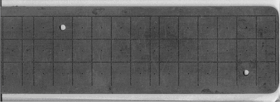
EXAMPLES OF MASTER PLATES
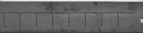
The first George V master plate. This was for sheet stamps with perforation from side to side. Made in 1911
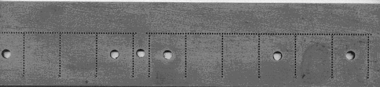
The first George V booklet master plate. Made in 1912
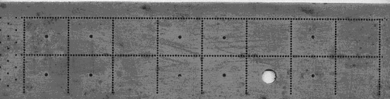
The first double pane master plate made in 1928. This was for sideways delivery rolls. Later in the year a further double pane perforator was made for end delivery rolls
Because of the length of the original master plates, only a small part can be shown here.
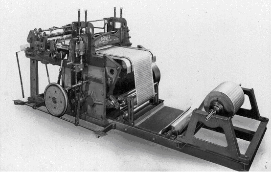
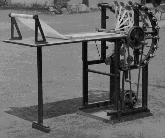
The original continuous printing machine designed by John Patient MBE of Somerset House and built by Grover’s in 1913. This was a typographic platen (flat-bed) printing machine. The paper was unwound by grippers and an unwinding drum to ensure exact registration of successive impressions of the plate. It was used for experiments into continuous printing of stamps from a reel of paper previously gummed and calendered, for use in stamp vending and affixing machines.
Many difficulties were experienced and it was not until the early 1920s that sufficient progress had been made for stamps to be printed by this means. These stamps were for the 1d value only and were used to make up the stamp rolls listed in Gibbon’s Specialised catalogue as SG N17A.
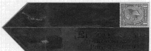
Leader with stamp produced at Somerset House
1930s continuous perforator for stamps produced in the web
Half of a triple comb booklet master plate
For making into stamp rolls for vending or affixing machines, the cutting operations were dispensed with and the work re-wound at the back of the machine, to be transferred to the reeling and splitting machine. The slitters cut the stamps into continuous strips evenly through the centres of the perforation, the starting ends of the strips being held individually on wooden cores of any desired diameter. At the point where the reels were to end, initially 500 or 1000, later 480, 960 or 1920 stamps per roll, which were ascertained by the number printed on the side margin during printing, a paper protective band was attached.
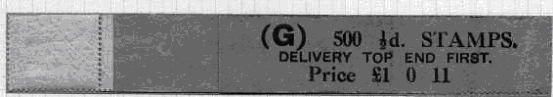
1912 trial roll showing the protective band, usually referred to as a ‘leader’. At this time rolls were made up from sheet stamps joined end to end
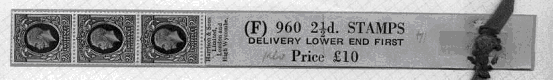
Leader with photogravure stamps produced from sheets perforated with the triple comb perforator, for bottom end delivery
Slitting and reeling machine for stamps issued in rolls
With continuous perforation the register is obtained by punch holes in the outside margins, three being punched at every revolution of the printing cylinder. These holes fit on to a moving chain, which regulates the passage of the web through the cylinder.
Perforating pins were available in many different sizes. One list seen has 36 different items available, although the majority of these were not for philatelic use. So far as Great Britain, and many overseas countries, was concerned, standard size definite stamps used No 1 pins (21.0mm long and .900mm wide) whilst the larger high value stamps used No 8 pins (21.0mm long but 1.020mm wide):/
No 8 perforating pins
Perforating (and printing) was always done in the opposite direction to the paper web – i.e. in the direction opposite to that of paper production. Machines were also capable of micrometer adjustment as distortion could (and did) occur during perforation runs. It was often found that because of atmospheric conditions sheets at the top and bottom of a ream of paper were distorted to a greater extent than those in the centre where they were more protected.
This information relates mainly to perforation during the period from 1910 and is based on the records of Grover & Co Ltd., manufacturers of printing and perforating machinery for almost 100 years, now alas no longer in existence.
Mention was made earlier of the Swedish ‘grinding’ method of perforation. Harrison purchased at least one of these machines from Sweden in the 1960s but it is not known if this was used to perforated British stamps, although they certainly perforated trial stamps using this machine, as a block of these trials exist. A description of the operation of this machine, taken from an advertising brochure, is shown below: